
")
")


Turbocharger Test Rig
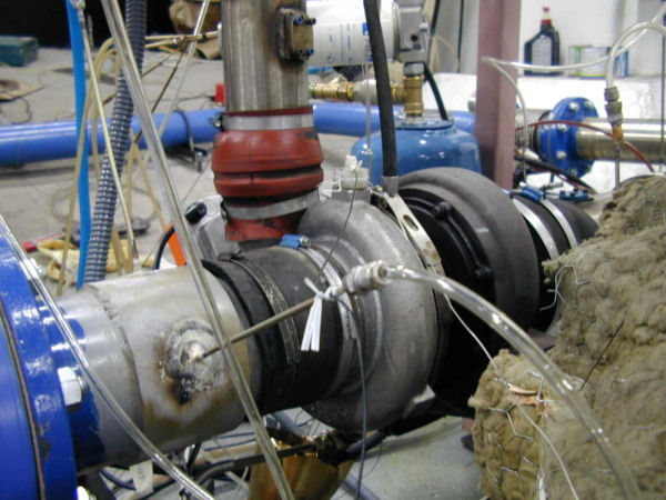
click to see more images
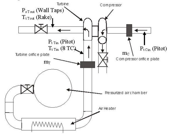
On this test rig the turbocharger under test is operated in an open circuit, while the inlet and outlet ducting is equipped with pneumatically driven throttle valves, which allow both inlet and outlet throttling. The turbocharger is driven from a pressurized air circuit. If desired, the compressed air is heated by an electric heater before fed to the turbine inlet. The hot gases that can be fed to the facility have the following characteristic upper limits: Mass flow rate: 0.8 kg/s, Pressure: 6 bar, Temperature: 300 C. The operating points for the compressor and the turbine are set by appropriate adjustment of the throttle valves covering the entire compressor and turbine performance map. The turbocharger is fitted with instrumentation allowing measurement of the quantities necessary to derive the compressor and turbine performance maps.
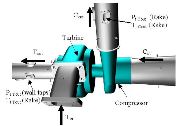
The compressor mass flow rate is measured with an orifice plate positioned at the compressor inlet duct. The compressor inlet total pressure is derived from a measurement upstream of the orifice plate, adjusted by the total pressure drop produced by the orifice plate. At compressor outlet, the total pressure and temperature are measured using pressure and temperature rakes, with five sensing points each. For the turbine mass flow rate, an orifice plate is also used. The turbine inlet temperature is derived from an average of 8 thermocouples positioned inside the tube. The total inlet pressure is measured using a total pressure Pitot probe. At the turbine outlet, a total temperature rake is used to measure the total temperature, while the static pressure is measured as the average pressure of four wall pressure-taps. Temperature is measured using type-K thermocouples and pressure by means of pressure transducers. The errors in performance variables of the compressor map are estimated to be 0.5 % in pressure ratio, 1% in efficiency, 0.8 % in mass flow rate and 0.1 % in rotational speed.