")
")


Contra Rotating Test Rig
click to see more images
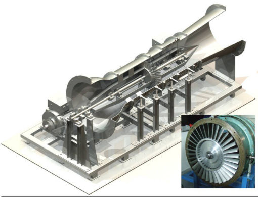
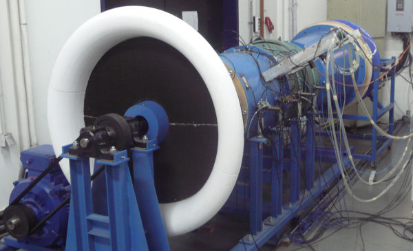
The Contra Rotating test rig (C-R) consists of a compressor stage with two contra rotating blade rows. The aim of this test rig is to determine the flow field characteristics and the performance of a contra rotating compressor stage.
The design of this test rig was carried in L.T.T. N.T.U.A., except the blades which are modified stator vanes from the 3rd stage of a GE J-79. The adjustable blades stagger angle, rotors axial position and rotors RPM, make possible the parametric analysis of this contra rotating stage.
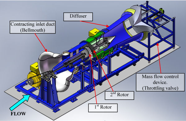
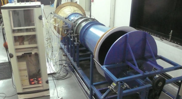
The rotors shafts are belt driven by two electric motors. The airstream enters the test rig via a contracting inlet duct (bellmouth) which has a honeycomb at its inlet for flow straightening. This combination provides uniform radial distribution of velocity, flow angle and pressure upstream the 1st Rotor. The flow channel has a constant height of 125mm and the blades tip diameter is 550mm. The blades tip clearance is 1.5mm. Downstream the compressor stage there is a diffuser for static pressure gain before the airstream exits the test rig radial through a transition cone, the axial position of which via an electric motor make possible the mass flow control.
The experimental equipment of the test rig includes:
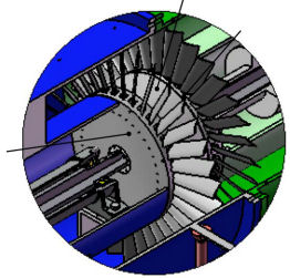
- Pressure transducers that are connected to the rig for static pressures measurement, as well as to 3 and 5-hole probes for radial distribution of pressure and velocity measurements, upstream and downstream each rotor. The bellmouth static pressure wall taps are located to its max and min diameter in order to determine the compressors mass flow rate through this differential pressure. The rest of the wall taps are located upstream and downstream each rotor for the determination of the mean static pressure there. Upstream the 1st rotor a 3-hole probe is mounted on a probe carriage which can move the probe radial. Downstream each rotor two 5-hole probes are mounted on two probe carriages which can move the probes radial and rotate them in order to measure the 3D flow field.
- 2 proximity sensors for measurement of rotors RPM via the measurement of each rotor blades pass frequency.
- 2 accelerometers near rotors axial position for measurement of vertical and horizontal vibration.
- A sensor for ambient pressure, humidity and temperature measurement.
- 2 microphones for noise emissions measurement.
- An ADC card and a PC for data acquisition.