
")
")


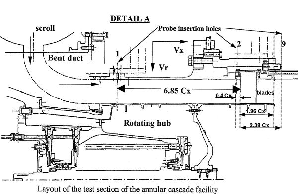
Annular Cascade Test Rig
click to see more images
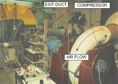
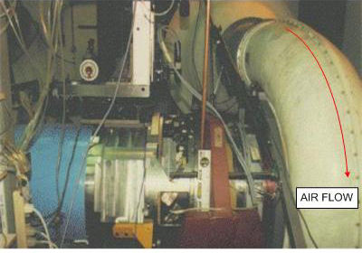
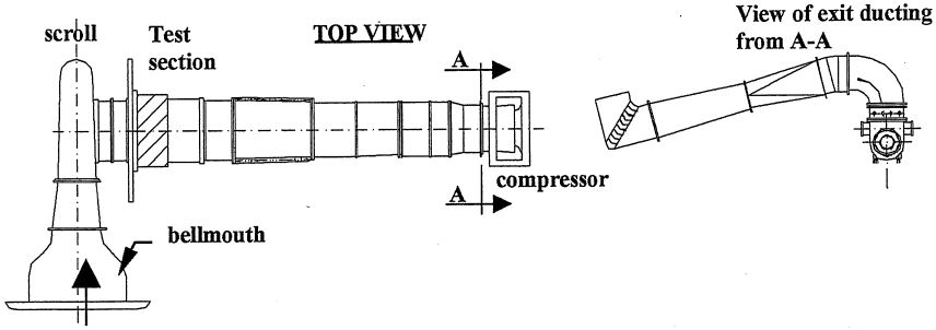
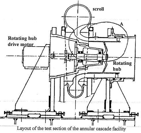
In this facility an axial compressor, placed downstream, induces the flow in the test cascade. The airstream enters the facility via a smoothly contracting bellmouth into a scroll, which delivers the air flow with a swirl into a contracting axisymmetric bent duct, leading to the annular space with hub–tip ratio of 0.75. The test section, on which the test cascade is mounted follows. The cascade has 19 untwisted blades of a chord of 100 mm, an aspect ratio of 0.8, maximum thickness-to-chord ratio of 4.58%, a solidity of 1.065 at midspan, and a 4% chord clearance gap size. The geometrical inlet and outlet angles of the blades are 60.1 and 44.6 deg from the axial direction, respectively (equivalent camber angle of 15.5 deg), whereas the stagger angle of the blades at midspan is 51.4 deg. The hub wall of the annular space can be rotated by a controlled speed electric motor, creating a relative motion between the endwall and the blade tip. The maximum local Mach number that can be achieved in the annulus at the cascade inlet is about 0.7, whereas the maximum peripheral Mach number of the hub wall is 0.51.